Making Design Decisions:
A Practical Example
by Bill Young, 100kGarages
I thought it might be useful to Makers to give you an example of how you can get something made working with a digital Fabber. Although the process will be unique for every project and design program that you use, and somewhat different depending on what type of digital fab tool your project will require, here are the steps involved in designing my first set of LinkerLogs (a building set kit for kids), and some issues related to digital fabrication with CNC that had to be considered. Even if your project is completely different than this, you may find the described steps helpful for your own design work, or for working with a Designer.
Step 1. Ideas and Inspiration
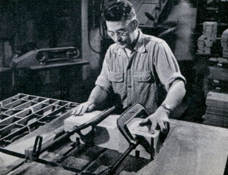
The LinkerLogs project evolved from an email from a friend, with a link to an article from a 1953 Mechanics Illustrated about a set of plywood building planks that were made using a traditional method ... a table saw. They seemed to be perfect for digital fabrication, which brought some modifications to mind that made them seem cool enough to me to really want to get them made:
- The pieces could be made more modular, with a uniform width and slot spacing so that it would be more versatile
- Corners could be rounded, making them a little easier on kids' hands
- Pieces with curves and odd angles could easily be added
- Modularity would make it easier for others to create parts that would fit accurately with all others, creating an open design standard
Step 2. Critical Decisions
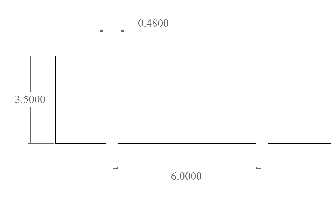
A couple of decisions had to be made about critical dimensions and it was important to make them early on. I knew I wanted the logs to be cut out of 1/2" plywood, but plywood and other sheet goods are almost NEVER the size and thickness they are supposed to be and I knew that the plywood that they would be cut out of averaged between 0.46-0.47" thick. If material thickness is important to your project, a quick email to the Fabber that you've selected will let you know the exact thickness of the plywood that they would be cutting. I didn't want the fit to be too tight for little kids to assemble and disassemble, or so loose that it was floppy, so I decided on using 0.48" for the width of the slots that kids would use to put them together.
Unlike the fit of the slots, the rest of the measurement decisions were a little more arbitrary and could be based on aesthetics, material usage, and things like ease of handling for the end user. Although the Fabber would be cutting the parts out of a standard 96"x48" sheet of material, I also wanted to be able to cut them out of 24"x48" blanks on some of the smaller size CNC routers in the 100kGarage community so that they could be made in a lot of different locations. So a maximum piece size of 4"x48" seemed about right. Since we would have to leave room for the width of cut, I decided on 3.5" wide planks, and this plank width dictated the depth of the slots, which had to be 1/4 of the width of the plank or .875". And 6" between slots seemed about right, with a 2" overhang on the ends. The design decisions were complete.
Step 3. Drawing the Parts and Adding Details
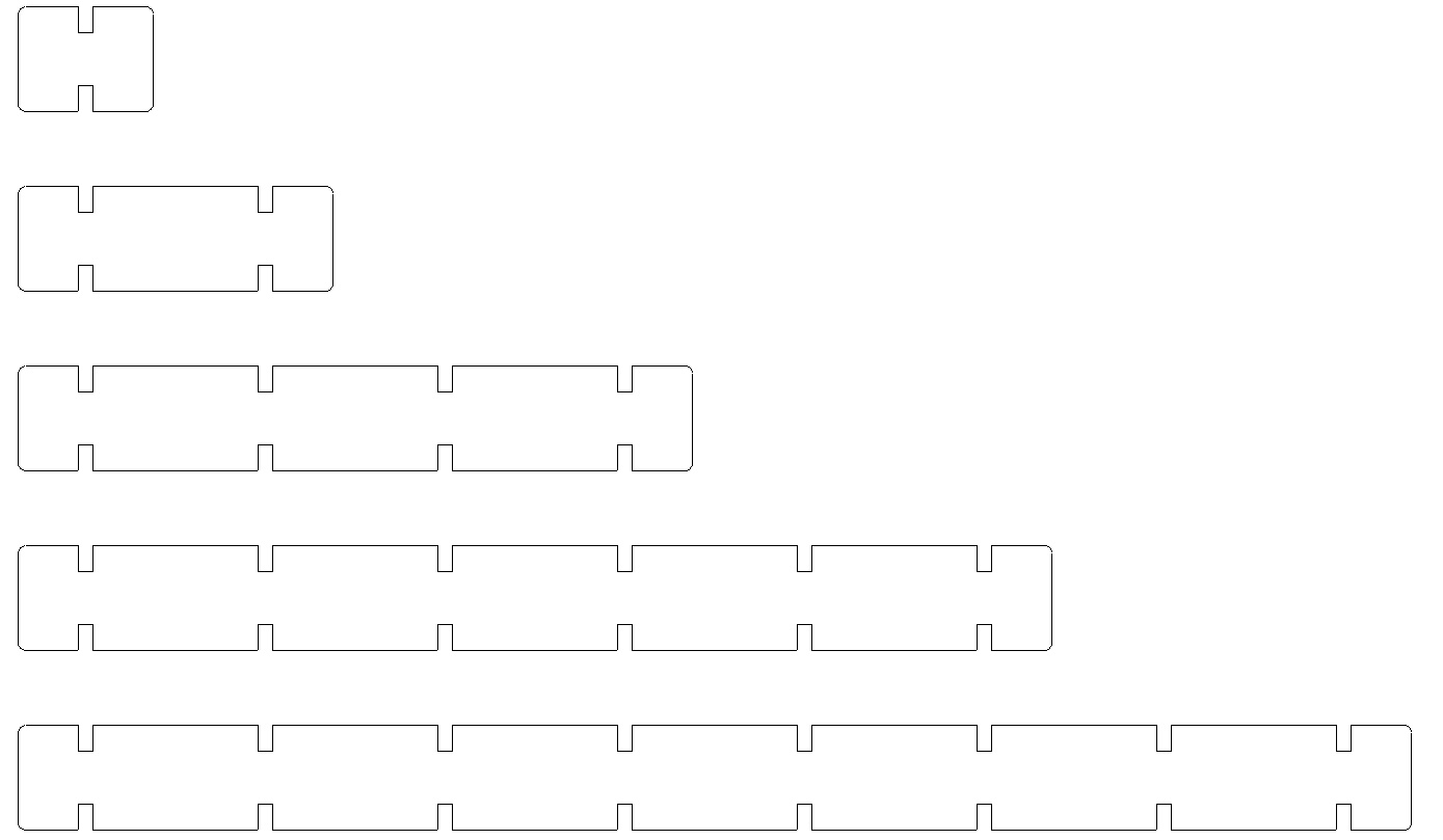
The next step was to decide on what set of sizes that would work well with standard plywood sheet sizes, based on the number of slots. An 8-slot piece ended up being about 46.5" long which would work nicely in both 4'x8' sheet material and 2'x4' blanks for smaller tools and not be too big for small kids to handle, so that became the longest piece. 6-slot, 4-slot, 2-slot, and 1-slot pieces filled out the set.
Fortunately, in my CAD program I only had to draw one pair of slots then used the "linear copy" tool with 6" between the copies to make as many pairs of slots as I needed for each particular size of plank. Lines were drawn connecting each set of slots using the "End Snap" tool, and ends were added with rounded "Filleted" corners to make them safer and easier to handle.
Step 4. Layout on the Material
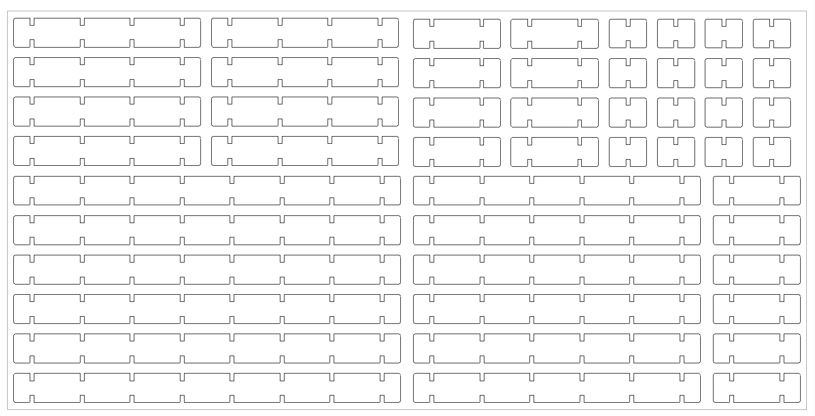
The final step was to lay out the parts on a 4x8 sheet of material, leaving enough room for the cutting bit between pieces and around the sheet template. Once again the quantity of each size piece was arbitrary... good enough for a first version.
Step 5. Get It Ready for the Fabber
All that was left to do was to send my file to the Fabber and give them any special instructions. Here are some of the things I had to consider:
- When a CNC tool, or anything with a rotating bit like a router, cuts an "inside" corner, it leaves a small arc in the corner that's the radius of the bit. In pieces that have to slot together like these pieces, this arc keeps them from seating "flat to flat." The solution is for the Fabber to create something called a dogbone in the corners, using their toolpathing software.
I could have created these dogbones while I was designing, but I would have had to make some assumptions about the bit that the Fabber would be cutting with. I decided that I would leave the dogboning to the Fabber, but made sure that they knew that I needed them and the style that I preferred. - My CAD program gives me the option of saving in several formats, so I asked the Fabber what their preference was. DXF was their preference, saved in an early version to make the file smaller and to leave out a lot of extra information that wasn't needed.
I zipped the dxf file (to help avoid data corruption when emailing) and then sent it to the Fabber for cutting.
In the Spotlight
The Project Board
A snapshot of current activity
- Custom Bushing...Open for Bidding
- Turn Cool Flat Illustrations into LES Window Display...Open for Bidding
- 555wincafe...Delivered
- Making CNC Fabricated parts ...Open for Bidding
- White Plains Center...Open for Bidding
Just browsing? See more projects.
See all open jobs and submit a bid.
Get your project made.

created by

our partners